|
1951 Chevy Accessories Installation Manual |
|||
 |
|||
|
|
|||
|
Figure 5 |
|||
|
|
|||
|
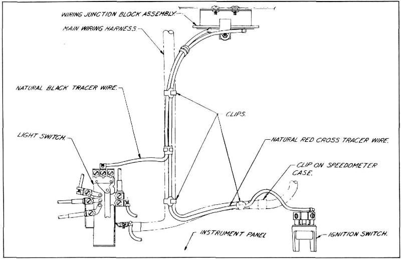
a. Natural red cross tracer wire to top
terminal on ignition switch.
(See figure
5).
b. Black tracer wire to one end
terminal
on light
switch. (See figure 5.) 4. Figure 4
shows suggested connections of various accessories.
Approximate Flat Rate Time .4
of an hour.
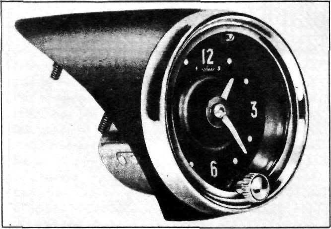
986526 ELECTRIC CLOCK
Procedure
for Installing Electric Clock on
Deluxe Model Passenger Cars. |
1. Remove clock furnished with vehicle by
inserting screw driver
into slot in edge of clock
frame to left of setting knob and prying until clock snaps free of retaining
springs, (see figure
7).
2. Place lead wires attached to back of
Electric Clock through
hole in clock housing and assemble clock to housing. Make sure that the
spring clips on the sides of the clock are aligned with slots in the housing and
the clock face is right side
up, (see figure 7).
3. Assemble wires in clips on back of
instrument panel and
connect the dial light lead to
the instrument light terminal on the light switch (see figure 7) and the clock power
lead to the lower center
terminal on the battery side of
the accessory junction block, (see figure 8).
Approximate Flat Rate
Time
Procedure
for Installing Electric Clock on
Special Model Passenger Cars,
1. Remove nut and washers from
two studs on underside of clock hole
cover plate. (Keep these nuts
and washers to reassemble clock to instrument
panel.) |
||
 |
|||
|
|
|||
|
Figure 6 |
|||
|
|
|||
| « PREVIOUS PAGE | CONTENTS PAGE | NEXT PAGE » |
|
|