|
1951 Chevy Accessories Installation Manual |
|||
 |
|||
|
|
|||
|
Figure 107 |
|||
|
|
|||
|
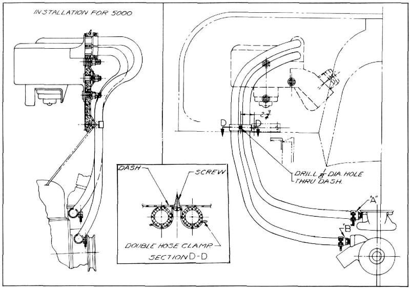
1. The
horns included in this package are equipped with brackets for mounting under
the hood on the engine dash.
Figure 108 shows the layout of
the installation and the location of the four 9/32" diameter holes
and the three 3/16" diameter
holes in relation to the
three existing holes in the engine dash. NOTE TYPE OF HEATER USED
FOR PROPER HORN LOCATIONS. See
figure 108. Drill the four
9/32" diameter horn mounting
holes as shown in figure 108. Loosen the dash mat fasteners and install
the reinforcements under the
dash mat against the panel on
the passenger side of the
dash. Fasten the horn mounting brackets on the projecting studs with the nuts
and lock washers furnished. See
figure 108.
2. On the
lower mounting stud of the upper horn
bracket and on the upper mounting stud of the lower horn bracket assemble the
ground lead clips. (Check
Heater installation and note
figure 108.) First, place one of the lock washers next to the horn mounting
bracket, then the ground lead
clip, followed |
by the
second lock washer and nut. See Section "A-A," figure 108. This places a
shakeproof washer on each side
of the ground lead clips to
insure a good ground connection,
3. Mount the horns
as shown on illustration (note position of projectors) with the low note horn above the high note horn and
fasten securely with nuts and lock washers furnished. The horns must be rigidly
mounted or the tone will
be affected.
4. To mount the horn relay, drill the two
3/16" diameter holes as shown
and secure relay in place using
two of the self-tapping screws included in the package. Assemble the third
terminal clip of the ground
lead under the head of the
relay mounting screw as shown. On vehicles using Recirculating
Heater, place center clip of ground
lead on Heater mounting stud as shown in the dotted line enclosed
area on the illustration. This
insures a good ground
connection for the horns. On vehicles using Recirculating Heater, place one of the
horn lead clips and lead from upper horn under this screw as shown in the dotted
lines enclosed
area. |
||
|
|
|||
|
41 |
|||
|
|
|||
| « PREVIOUS PAGE | CONTENTS PAGE | NEXT PAGE » |
|
|