|
1951 Chevy Accessories Installation Manual |
|||
 |
|||
|
|
|||
|
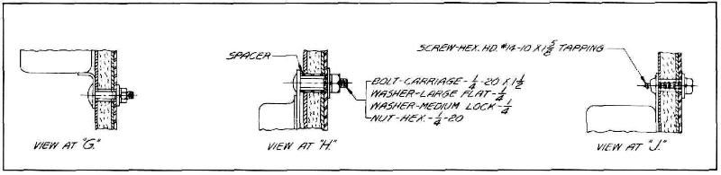
Figure 82 |
|||
|
|
|||
|
ficiently large hole in dash mat
at the large grommet so the cable can
make a smooth curve at this
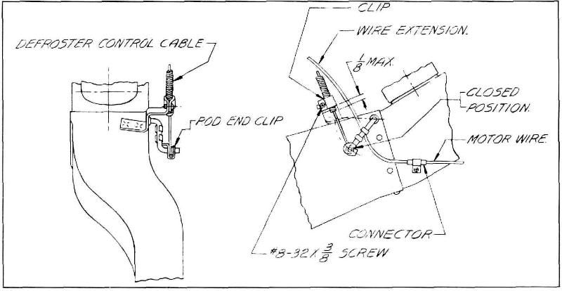
point. Mount cable bracket as shown in view at "L." Slide the
longest control cable through
the grommets in the dash and
dash leg, then rotate the valve to the position shown in view at "L" and assemble
the cable to the valve lever
using the rod end clip
provided. Secure the cable to bracket using: clip and screw. Rotate defroster
valve lever to the "closed"
position and attach the
shortest control cable to the lever using the rod end clip. Secure cable to
bracket using clip and screw.
See view at "K."
Control Unit: Remove the two nuts
and lockwashers used to hold the
left-side of the radio grille
and remove heater control screen. See view at "M." Before mounting
control unit in place,
assemble the fuse, fuse holder body and switch wire. Then
connect this assembly and the
motor extension |
wire to the switch. Attach
securely the loose ends of the control cable conduits. With air valve, defroster valve and temperature
control valve in closed
position and with the top edge
of the three levers even with the scribe mark on the face of the control,
tighten cable wires
securely. Check operation for
complete opening and closing of valves. See view at "N." Raise control unit with
wires and cables attached up
into place back of instrument panel and attach to instrument panel
using nuts and lockwashers previously removed. Attach the knobs to the levers
with the #6 flat head screws as
shown in view at "N." Connect heater switch wire to Junction Block as shown in view at "P."
Strap heater switch wire to main wiring harness using three existing straps. Attach
motor extension wire to
connector on front of heater,
then assemble this wire and two control cables to dash mat with closed clip
as shown in view at
"U." |
||
|
|
|||
 |
|||
|
|
|||
|
Figure 83 |
|||
|
|
|||
|
32 |
|||
|
|
|||
| « PREVIOUS PAGE | CONTENTS PAGE | NEXT PAGE » |
|
|