|
1951 Chevy Accessories Installation Manual |
|||
|
1. Disconnect wires and remove neutral safety
switch from lower end of
steering column as shown in
figure 121.
2. Place gearshift in neutral position and
mount combination back-up and
neutral safety switch
(furnished) with same mounting parts removed from equipment switch. DO NOT
REMOVE COTTER PIN FROM POWER
GLIDE
SWITCH.
3. Reconnect neutral safety wires to Power
Glide switch. Remove cotter pin from switch.
WIRING PROCEDURE
CONVENTIONAL-POWER GLIDE
1. Run wires through existing clip on dash as
shown in figure
121.
2. Run fuse wire through grommet in dash and
hook to Junction Block as
shown in figure 121. For
hook-up to Accessory Junction Block see figure 121.
3. Run long wires along inside of
flange of frame side member to
four-way connector at rear of
vehicle. Clip to inside flange of frame in eight places with clips
furnished.
MOUNTING OF BACK-UP LIGHTS TO BODY
1. Locate drilling position on
Styleline by measuring 23-3/4
inches from center of license bracket to each side of body from the stone
guard on rear bumper measure
up 3-5/8 inches and where
lines cross center punch. From
this point measure up toward trunk opening 1-11/32 inches and drill 1/4 inch
hole as shown in figure 122. At
first center punch mark, drill
1-13/16 inch hole for back-up
lamp, as shown in figure 122, repeat on opposite
side. |
2. Same procedure for Fleetline except the
following:
Measure 22-3/4 inches from
license lamp as shown in figure
122.
3. Assemble lamps to body and connect wires to
four-way connectors as shown in figure 122.
Approximate Flat Rate
Time .9 of an hour. 986489 GLOVE
COMPARTMENT LIGHT
Procedure
for Installing
Glove Compartment
Light
on All Model Passenger
Cars. |
||
 |
|||
|
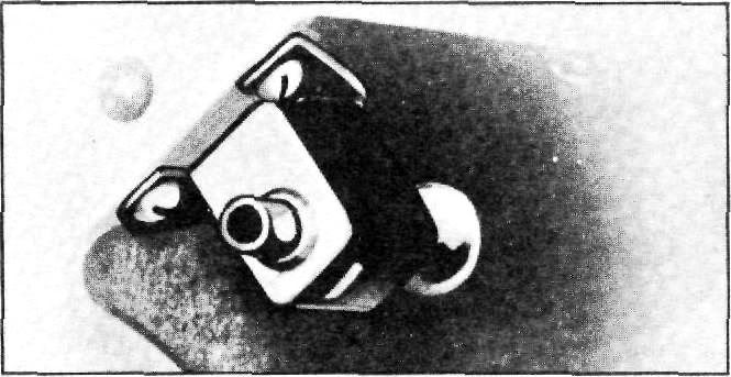
Figure 126
1. Install switch in hole provided in upper
left-hand corner of glove
compartment with screw provided.
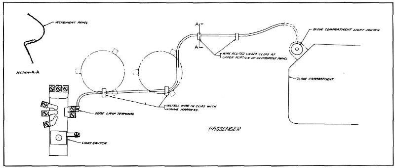
2. Install wire to clips provided on instrument
panel. (See figure
125.)
3. Connect wire to dome lamp terminal on light
switch. (See figure 125.)
Approximate Flat Rate Time .2 of
an hour. |
|||
|
|
|||
 |
|||
|
|
|||
|
Figure
125 |
|||
|
|
|||
|
53 |
|||
|
|
|||
| « PREVIOUS PAGE | CONTENTS PAGE | NEXT PAGE » |
|
|